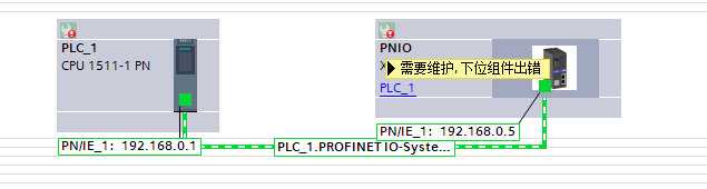
The diagnostic indication on the Solidot Remote I/O Module XB6S PROFINET Coupler suggests maintenance is required. How can this be resolved
During the debugging of actual projects for the Solidot Remote I/O Module XB6S PROFINET Coupler (model XB6S-PN2002), a situation may occur where all the connected rear I/O modules are successfully configured and network communication is established normally, yet the coupler displays a "Maintenance required, sub-component error" message.
This happens because, although the coupler itself is operating correctly, one or more of the connected remote I/O modules has encountered a fault or configuration anomaly. The diagnostic information from these sub-modules is reported collectively to the XB6S-PN2002 coupler, triggering the maintenance alarm at the coupler level. This article addresses such scenarios by explaining how to use the diagnostic information to pinpoint the specific problematic module and the corresponding resolution methods.
I. Preparation
Locate the module configuration interface and open the Device Overview.
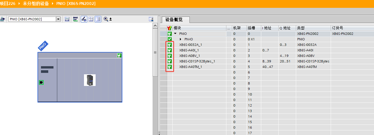
Once expanded, you will see all the sub-module models and their status indicators.
Modules with normal status display a green check mark.
Modules with a warning display a small wrench icon.
Find the relevant sub-module and double-click the wrench icon to open its detailed diagnostic information.
II. Common Issues and Solutions for Various Sub-modules
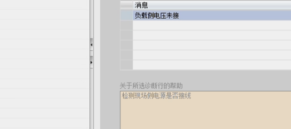
XB6S-0032A Module
Situation: As an output module, it requires a load-side power supply, which was not connected during our test.
Diagnostic Message: Indicates that the load-side power supply is missing.
Solution: Please check the power supply wiring.
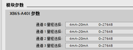
XB6S-A40I Module
Situation: The range was set to 4-20mA, but a 21mA input signal was applied during testing.
Diagnostic Message: Channel over-range or under-range error.
Solution: Check whether the input signal exceeds the measuring range.

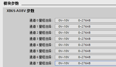
XB6S-A08V Module
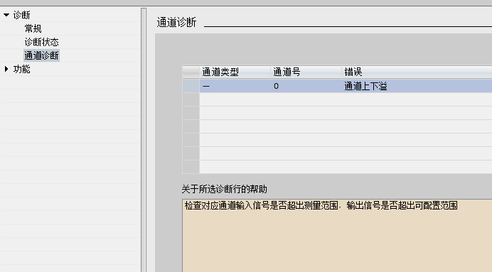
Situation: The range was set to 0-10V / 0-27648, but an output value of 30000 was given, exceeding 27648.
Diagnostic Message: Channel over-range or under-range error.
Solution: Check whether the output signal exceeds the configurable range.

XB6S-A40TM Module
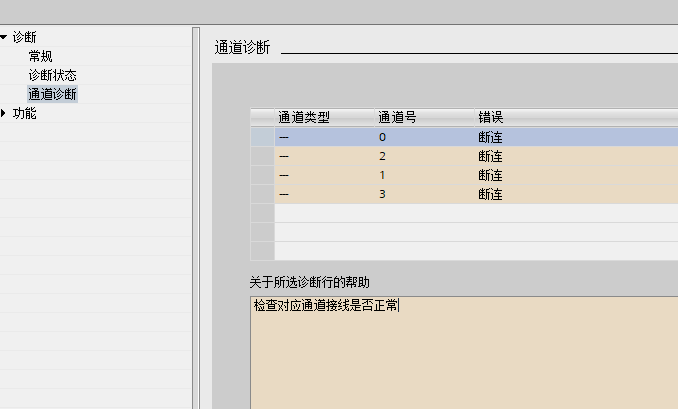
Situation: The channel was enabled, but no sensor was connected.
Diagnostic Message: Wire break alarm.
Solution: Check if the wiring for the corresponding channel is correct.
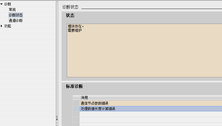
XB6S-C01SP Module
Situation:
Parameter 1 for Node 1 in this example was incorrect and meaningless.
The meaning of the parameters for Node 2 and Node 3 were both 'read 16 registers'. Combined, this exceeded the module's set limit of 32 bytes.
Diagnostic Messages: "Communication node parameter error" and "Process data length calculation error".
Solution: Check and correct the parameter configuration for the communication nodes.
With the guidance provided by these diagnostic messages, we can target and resolve the specific issues effectively.